So, this project has been a put on a shelf for a while, but what’s happened in 4 years?
Several things–most notably we’ve moved out further into the suburbs, and the loud sounds seem to have mostly abated. Whereas at the old place, I was pretty much guaranteed a loud sound every few days, but here I’m limited to a few clusters of booms around the 4th of July and New Year’s Eve, with very little else in the way of sample data. I don’t think my new neighbors would appreciate my setting off fireworks just to have sample data. I like to tell myself that the sounds at the old place were fireworks, but the reality was more likely a mixture of gunshots and fireworks.
Second, I’ve just lost steam on this. The problems with getting the timing right and other things like that have convinced me that maybe I need to re-think the microphone design. I’m thinking of using a dedicated GPS module on each microphone unit to establish both location and time more accurately, but that pushes up the cost considerably. GNSS/GPS receivers can be had for $30 or $35 dollars on convenient breakout boards, but that nearly doubles the cost per microphone. At that point maybe I should consider using a Raspberry Pi Zero 2W or similar, though the lack of analog inputs is problematic.
I’m starting to tackle the problem of identifying the individual sounds and correlating them with things detected by all the microphones. In order to do this I’m going to come up with abstractions for the data at each stage in the process. I’m going to start designing this from the bottom up. The terms for each abstraction are presented in bold the first time it is used.
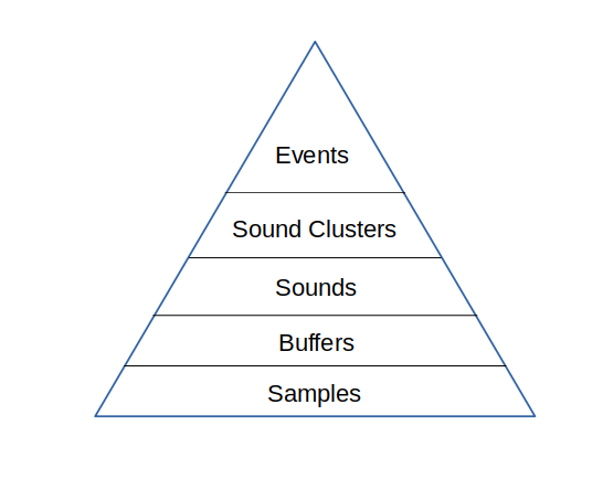
The hierarchy of abstractions
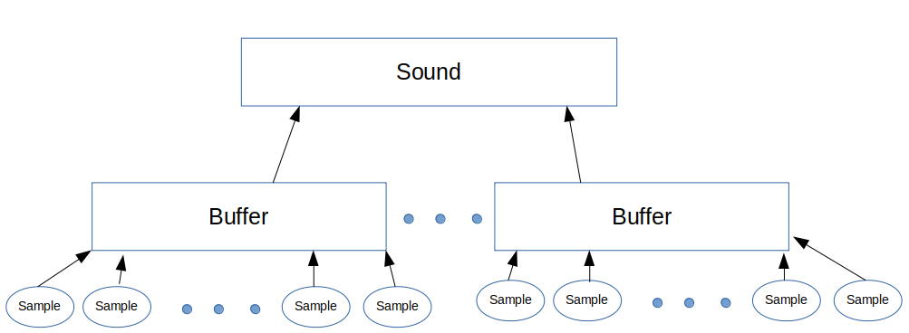
At the base of the pyramid of abstractions are samples. These are individual measurements of the voltage the microphone element produces. The samples are grouped together into buffers. Currently the size of a buffer is 512 samples, collected at approximately 20kHz. The microcontroller decides if the buffer is interesting by looking for samples where the voltage falls above a threshold. If interesting, it then forwards that buffer and preceding and following buffers to the server.
The server receives these sound buffers from an individual microphone controller. The server groups these buffers together based on time. Each buffer spans about 22 milliseconds, and buffers from the same controller that arrive within 50 ms of each other are considered to be part of the same sound (50 ms chosen so that 1 or 2 dropped buffers don’t break up a single sound.)
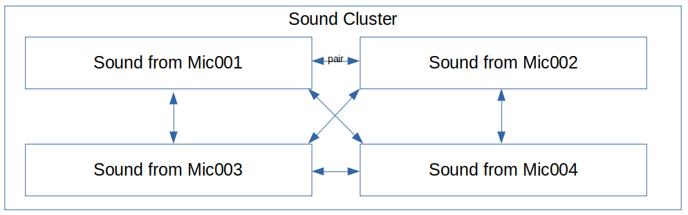
Sounds from different microphone controllers are grouped together by the server into sound clusters that occur within some small time frame that will be bounded by the time it takes for sound to travel between microphones (plus some small amount to allow for timing errors.) If the sound cluster contains sounds from more than 2 microphones, it will be considered to have originated from the same event.
The server then tries to determine where the event happened. It does this by calculating the time-offsets and similarities of each pair of sounds in a cluster. If the similarity of a pair of sounds falls below some threshold then the time-offset for that pair will be discarded. The remaining time-offsets for a cluster will then be combined the the physical arrangement of their corresponding microphone assemblies and used to calculate a best-guess for the location of the event.
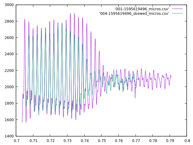
After writing up my (computationally intensive) code to measure the skew between the signals from two microphones, I’ve made a discovery. It works great for stuff with complex, low-frequency sounds like my chair creaking, but not so well in other cases. For sustained, constant frequency sounds (like beeps) it gets confused about which of several possible alignments are “best”. Take for example this short beep as heard by two adjacent microphones:
My visual best fit says the green waveform needs to be shifted a few hundred microseconds to the right, and that these were almost in alignment already. However, my algorithm shifted it ~13,000 microseconds to the left.
It did make the wave peaks line up, but since this is a more or less steady tone, that happens every couple of milliseconds. I’m also sure it maximized my fit function, but to my eye the overall envelopes don’t match nearly as well. I think there are two factors working against my algorithm here. First, the waveforms weren’t complete–the beginning of the waveforms was cut off by different amounts in the different samples. I’ve taken measures to reduce the likelihood of that happening, but I can’t eliminate it altogether. Second, this was a fairly steady tone–as I already mentioned, and there were lots of “pretty good” fits that it had to choose from.
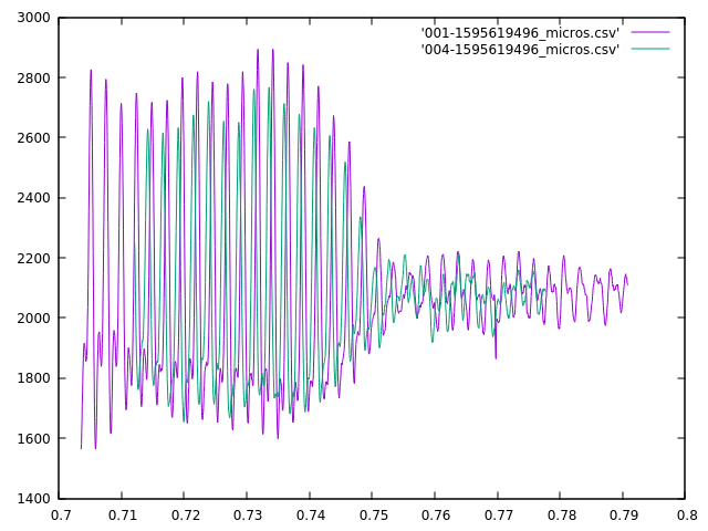
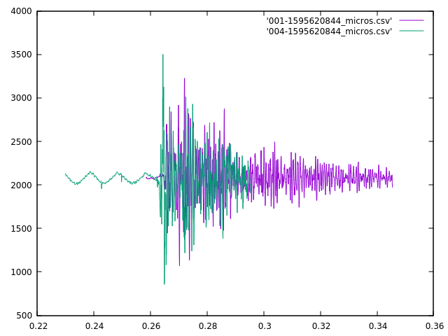
The other situation that it doesn’t handle well is more problematic. It appears that for short, sharp sounds–like a clap, whip crack, fireworks or gunshots–there is too much high-frequency information that the two mics will sample differently, and since my sampling rate is about 20kHz, I really can only differentiate frequencies below about 10kHz (5kHz for a good fit). See the Nyquist-Shannon theorem for a more complete discussion as to why. So, when I have a signal with a lot of high-frequency information, I can’t really match it effectively. Take this example of a clap when the mics where a few feet apart (1-2 meters):
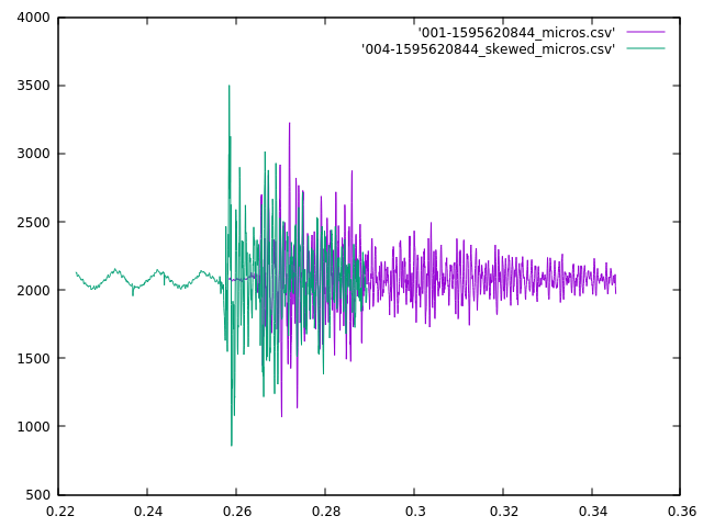
The apparent shift shouldn’t need to be large, but the algorithm doesn’t pay attention to that, and it came up with a fit that looked like:
This is a much worse fit according to my eye. I think a better technique in this case it to line up the beginning of the loud sounds, but I need to come up with a way to identify those algorithmically. I’ll probably use some heuristic like looking at the time of the first samples to fall significantly further from the mean than I’d been seeing previously, but that requires that I have a nice quiet section before the sound happens. I’ve taken steps to try to make sure that I have that (by sending the prior buffer as well when I detect an anomaly), but it doesn’t always work out as you can see in the purple curve.
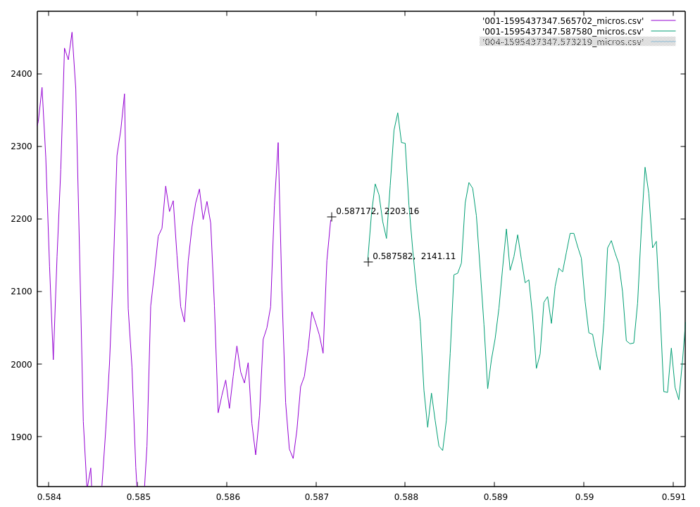
The downside to increasing the sample rate is that I also increased the timing error that accumulates during a sampling buffer. Look at these sequential data buffers:
I’ve got a gap
There’s a gap of more than 400 microseconds between the last measurement of the first packet and the first measuement of the second. That gap isn’t real though. There’s actually about a 42-43 microsecond gap in real time, but because I send the measurement interval as a whole number of microseconds between messages, there’s a fraction of a microsecond that gets lost to truncation. In this case, the actual interval of 42.72 microseconds gets truncated to 42 microseconds when sent to the server, and that means that there’s about a 370 microsecond error by the end of the packet (0.72 microseconds * 512 measurements in the packet).
Currently the measurement packet has a 22 bytes of header, including both the timestamp of the beginning of the packet (8 bytes) and the number of microseconds between measurements (2 bytes). I could redesign the measurement packet so that the same two bytes pass 100ths of microseconds rather than whole microseconds, and that would allow up to 655.35 microseconds as a measurement interval without changing the overhead of the packet. (I’ve only got about 1450 bytes to work with in a UDP packet that’s going to travel over WiFi and Ethernet, so I’m trying to be frugal with headers and leave as much space as possible for actual measurements.)
A big part of the success of this project will hinge on getting all the microphones to agree on what time it is. I don’t really care if that time is particularly accurate, as long as all the sensors agree on it. Of course, they’ll never agree exactly, but if I can get them in agreement to within 50-100 microseconds, that should be good enough.
I’ve starting experimenting with the Network Time Protocol (NTP). In theory, this should be satisfactory for what I’m doing. However, the implementation I’ve found for Arduino based systems is pretty basic, and doesn’t implement the full protocol. First, it only exposes the whole number of seconds, and doesn’t expose the fractional part of the seconds. I’ve modified it to expose down to microseconds. Second, it simply takes t2 of the clock synchronization algorithm. It doesn’t do the full offset and round trip delay calculation. This is good enough if all you care about is rough accuracy (+/- 1 second), but apparently isn’t sufficient for what I need. But even if I extend the library further I may not be able to achieve the accuracy I need.
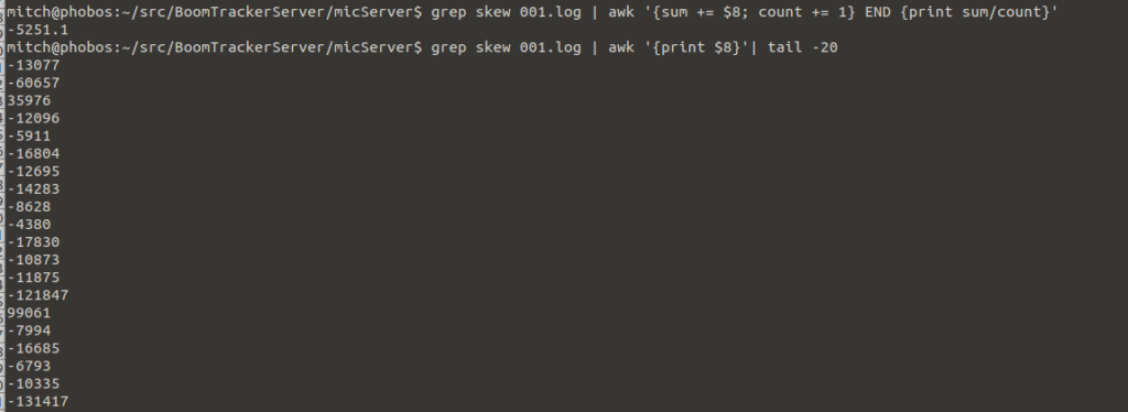
I have my devices syncing to the NTP server on my home box every 10 seconds or so, and I’ve had them log the amount of skew (change in current time) they are seeing every refresh. Over long stretches, it averages about 5,000 microseconds fast per 10 seconds of clock time–which is pretty good and easily compensated for, but individual skews are all over the place. It jumps back and forth by 5,000-120,000 microseconds (5-120 miliseconds) at a time. Keep in mind that with a 20 meter baseline, the delta time is at most 52ms, and usually much less.
What I’m seeing in the logs
This might partly be due to the differing transmission delays that the algorithm currently ignores, (that’s one reason I’m syncing to a local server, to minimize the transmission delays), but 120ms is a pretty big transmission delay for a local network, and is closer to what I would expect for US to Europe round trip.
So what are the sources of error?
The shortcomings in the current library.
The stability of the clock on the microcontroller.
The stability of the clock on the server.
The inevitable jitter caused by the vagaries of WiFi.
Of those, I can only address the first three sources of error. Time will tell if that’s good enough.
When I priced out the BeagleBoard Black design, I didn’t know that there was a cheaper BeagleBoard available. It’s the same price at the Feather M0 WiFi, and it’s got several analog inputs, plus I can run Linux on it. The only thing it doesn’t have is WiFi, but there’s a USB port available, and a second one can be attached. So I’d just need a $5 WiFi dongle and a microphone , and I’d be all set.
I want to clarify what I’m trying to accomplish, and what I’m specifically not trying to accomplish. Commercial versions of this technology do a sophisticated analysis of the sounds they detect, so that they can do things like distinguish between fireworks and gunshots using shock wave profiles and such.
At least for this first iteration, I’m not looking to do anything nearly that complex. I just want to be able to pinpoint any loud sound in a reasonable range. Future iterations may do something as subtle as attempting to disentangle overlapping sounds, or deal with long continuous sounds (like a running motor, jackhammer, etc.), but those are stretch goals.
The microphones don’t need to be particularly fancy–all I need them to do is identify loud sounds. I’m considering these. Far more critical is identifying when those loud sounds occurred very precisely. Actually, I don’t care about the absolute time, just the relative time each microphone receives the sound.
As we saw in the first post, with a baseline of 20 meters (~65 feet)–which is about all I can fit in my back yard, a 1 millisecond difference translates into about a 1 degree difference in direction, and that resolution isn’t good enough to pinpoint something more than a few houses away. I’m shooting for having a resolution of 100 microseconds (and an angular resolution of 1/10th of a degree.) This would require a 10kHz sampling rate, which is about all I can get without going with exotic hardware.
I could use a single computer with an accurate clock to monitor all four microphones directly. This is the simplest solution, but practical limitations on how long you can make the microphone cables and difficulty routing them mean that I’d be limited to relatively short baselines. I may build a simple proof of concept based on this design, but it’s far from ideal.
A more capable solution is to have a small single board computer with each microphone, having them report back to a central host and synchronizing their clocks using WiFi. A linux based computer like a Raspberry Pi or a BeagleBone might work, but the problem is better suited to a dedicated microcontroller with WiFi like the Adafruit Feather HUZZAH–built around a ESP8266 microcontroller, or perhaps an Adafruit Feather M0 WiFi, which has considerably more memory and features, though it’s roughly twice the price–making it nearly as expensive as a Raspberry Pi 3 B. Here’s a table of the trade-offs
Name
Analog inputs
Clock
WiFi
Battery Management
Total price/mic
Raspberry Pi 3 B+
0
Y
b/g/n/ac
N
$60
BeagleBone Black
8
Y
dongle
N
$80
Feather Huzzah
1
N
b/g/n
Y
$30
Feather M0 WiFi
8 (6 usable)
RTC
b/g/n
Y
$55
Microphone computer options
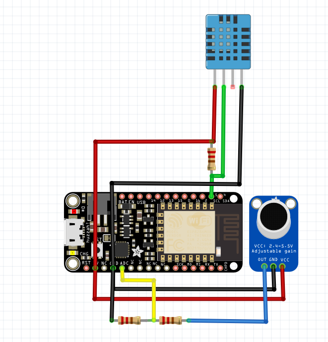
The HUZZAH only has one analog input (with a 1v maximum so I’ll have to use a voltage divider to drop the 3.3v mic output down), and I’m not sure that it has enough memory to handle the WiFi, NTP and the audio code combined. I’ve ordered one to give it a try. Here’s a basic design I came up with (the blue package at the top is a temperature sensor so I can calculate the speed of sound):
Feather HUZZAH ESP8266 microphone design
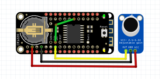
The M0 WiFi variant on the other hand, has lots of analog inputs and memory. I’m going to interface it with a RTC (real time clock) chip. The RTC only has a resolution of 1 second for direct measurements, but also provides temperature compensated oscillator which can generate 32kHz, 8kHz, 4kHz, 1kHz and 1Hz square waves, which should allow for some relatively precise measurements. The 8kHz clock would give me a resolution of approximately 125 microseconds, which is pretty close to what I’m looking for. The 32kHz clock could give me a resolution of ~30 microseconds, but the ADC (analog to digital converter) on that cheap chip almost certainly can’t match that rate. The RTC also has the ability to measure temperature. I’ve ordered one of these as well and I’ll do a head-to-head matchup to see which will work better. The relatively hefty price means building 4 M0 boards (with 4 RTCs and 4 microphones) will strain the budget.
Feather M0 WIFi microphone design
Both of the feather boards have battery management, so I might be able to get away with making them battery/solar powered, meaning even fewer wires to deal with. The range of the WiFi limits the baselines to no more than a hundred to two hundred feet (30-60 meters). For longer baselines I’m considering using the LoRa radio version of the Feather, which might allow for baselines measured in kilometers rather than meters.