Designing the microphones

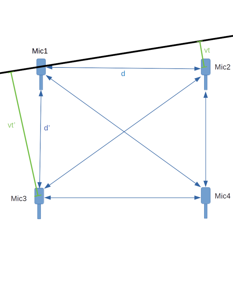
The microphones don’t need to be particularly fancy–all I need them to do is identify loud sounds. I’m considering these. Far more critical is identifying when those loud sounds occurred very precisely. Actually, I don’t care about the absolute time, just the relative time each microphone receives the sound.

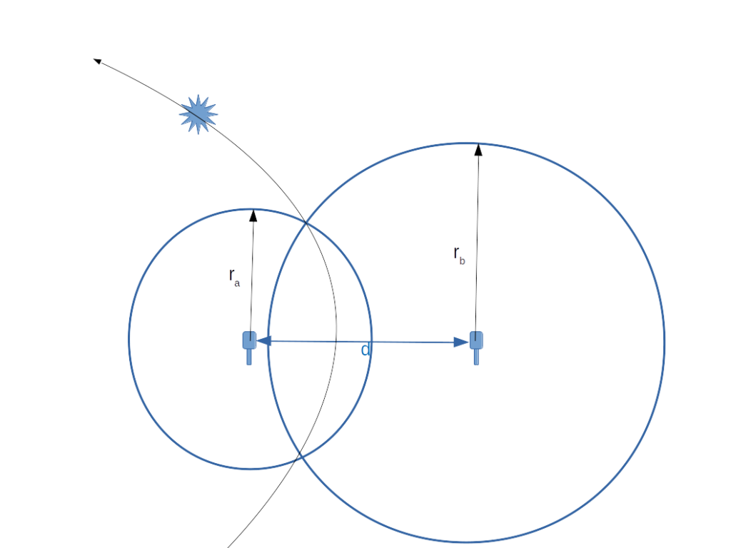
As we saw in the first post, with a baseline of 20 meters (~65 feet)–which is about all I can fit in my back yard, a 1 millisecond difference translates into about a 1 degree difference in direction, and that resolution isn’t good enough to pinpoint something more than a few houses away. I’m shooting for having a resolution of 100 microseconds (and an angular resolution of 1/10th of a degree.) This would require a 10kHz sampling rate, which is about all I can get without going with exotic hardware.

I could use a single computer with an accurate clock to monitor all four microphones directly. This is the simplest solution, but practical limitations on how long you can make the microphone cables and difficulty routing them mean that I’d be limited to relatively short baselines. I may build a simple proof of concept based on this design, but it’s far from ideal.

A more capable solution is to have a small single board computer with each microphone, having them report back to a central host and synchronizing their clocks using WiFi. A linux based computer like a Raspberry Pi or a BeagleBone might work, but the problem is better suited to a dedicated microcontroller with WiFi like the Adafruit Feather HUZZAH–built around a ESP8266 microcontroller, or perhaps an Adafruit Feather M0 WiFi, which has considerably more memory and features, though it’s roughly twice the price–making it nearly as expensive as a Raspberry Pi 3 B. Here’s a table of the trade-offs

NameAnalog inputsClockWiFiBattery ManagementTotal price/mic
Raspberry Pi 3 B+0Yb/g/n/acN$60
BeagleBone Black8YdongleN$80
Feather Huzzah1Nb/g/nY$30
Feather M0 WiFi8
(6 usable)
RTCb/g/nY$55
Microphone computer options

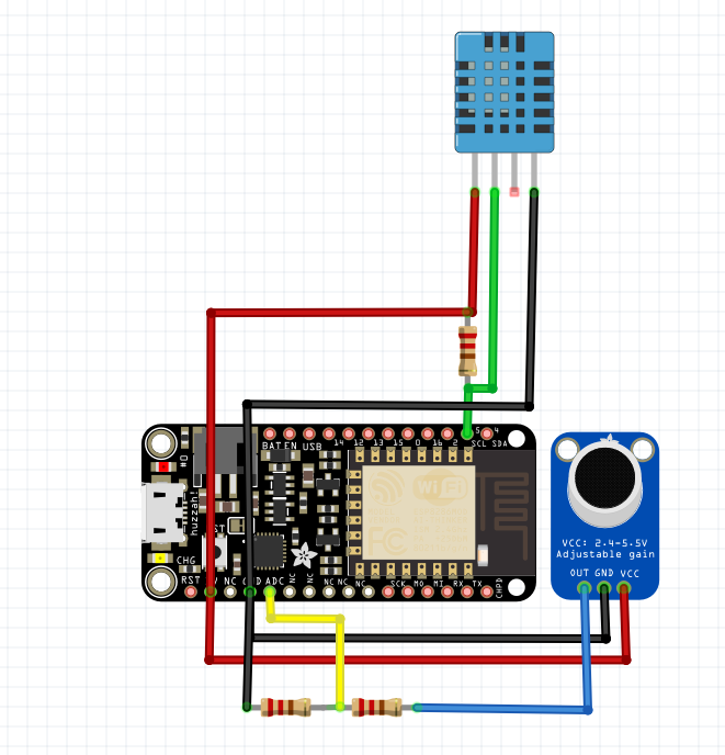
The HUZZAH only has one analog input (with a 1v maximum so I’ll have to use a voltage divider to drop the 3.3v mic output down), and I’m not sure that it has enough memory to handle the WiFi, NTP and the audio code combined. I’ve ordered one to give it a try. Here’s a basic design I came up with (the blue package at the top is a temperature sensor so I can calculate the speed of sound):

Feather HUZZAH ESP8266 microphone design

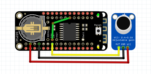
The M0 WiFi variant on the other hand, has lots of analog inputs and memory. I’m going to interface it with a RTC (real time clock) chip. The RTC only has a resolution of 1 second for direct measurements, but also provides temperature compensated oscillator which can generate 32kHz, 8kHz, 4kHz, 1kHz and 1Hz square waves, which should allow for some relatively precise measurements. The 8kHz clock would give me a resolution of approximately 125 microseconds, which is pretty close to what I’m looking for. The 32kHz clock could give me a resolution of ~30 microseconds, but the ADC (analog to digital converter) on that cheap chip almost certainly can’t match that rate. The RTC also has the ability to measure temperature. I’ve ordered one of these as well and I’ll do a head-to-head matchup to see which will work better. The relatively hefty price means building 4 M0 boards (with 4 RTCs and 4 microphones) will strain the budget.

Feather M0 WIFi microphone design

Both of the feather boards have battery management, so I might be able to get away with making them battery/solar powered, meaning even fewer wires to deal with. The range of the WiFi limits the baselines to no more than a hundred to two hundred feet (30-60 meters). For longer baselines I’m considering using the LoRa radio version of the Feather, which might allow for baselines measured in kilometers rather than meters.

Better Theory

As I mentioned at the end of the last post, I’ve been assuming that the sound wave was flat, when in fact it is round. now as long as the distance to the source of the sound is much larger than the distance between the two microphones, then this is a pretty good approximation. But what if the source is closer? Consider this:

Now the difference in times is t=(|r2|-|r1|)/v, but we don’t know either r1 or r2, only their difference. We can try to solve for all the places where the difference in the distances is that value. Starting with the point along the line connecting the two, we can find all the points where difference in distances is vt:

v*t=rb-ra and rb+ra=d, so rb=(d+v*t)/2 and ra=(d-v*t)/2

I’ll spare you the detailed math, but the solution for possible locations is one branch of a hyperbola:

When the difference of the radii of two circles is a constant, their intersections trace a hyperbola
The intersections of all the circles where the radii are a constant difference is a hyperbola

In the limit, you may remember that a hyperbola asymptotically approaches a pair of lines (called asymptotes). These asymptotes are the approximations from my last post. However, with just the measurement from these two microphones, we couldn’t pin down the source any more accurately than somewhere along the hyperbola, but again if we use more than two microphones, we get multiple hyperbolas, and those should only intersect at one point. (hopefully)

Theory

The basic idea behind this project is to use an array of microphones to measure the relative time of a sound. Then, using the locations and arrangement of the microphones, we should be able to calculate where the sound originated.

Here’s how this will work. Let’s assume we have two microphones on an east-west line a distance d apart, and a sound wave is propagating past them at an angle Θ. Assuming we know the speed of propagation v, we can take the time difference t of the arrival at the two microphones, and calculate what Θ must be. It looks like the diagram at the top of the every page on this site:

So Θ=arcsin(v*t/d) and that gives us a rough direction to the source of the sound. The distance d can be measured with a measuring tape. The time difference t can be measured by a computer, and the velocity of sound can be calculated if we know the air temperature. Let’s assume some values to see it in action:

d = 20 meters (approximately 65 ft for those playing in the US)

v = 343.3 meters/second or 1126 feet/second (at 20°C / 77°F )

t = 1 millisecond = 0.001 seconds

So Θ = arcsin(343.3*0.001/20) = 0.01717 radians which is just a little less than 1 degree of arc.

Since the microphones are set on an east-west line, that means that the direction to the source of the sound is 1 degree west of north, or 359°.

Clever people will notice that I’ve glossed over a critical detail. I’ve assumed that the wave is propagating from the top of the page, rather than from the bottom. If it were propagating from the bottom, then the timing would be the same, but the bearing to the sound would be 1 degree west of south, or 181°. How do we figure out which of those is correct?

The answer is using more than 2 microphones. Let’s assume we had 4 microphones arranged in a square like so:

sound wave propagating past an array of 4 microphones
Full Array

The time between the arrival at Mic1 and Mic3 is here represented as t’, and and distance is represented by d’. Using similar logic to that above, if t’ = 58.2 milliseconds, and the distance is the same, then the bearing from these two mics is either 358° (if coming from the upper left) or 2° (if coming from the upper right). Since 358° and 359° are about the same, we can deduce the correct answer. Actually, with 4 microphones we have a total of 6 baselines to calculate with.

There’s only one problem left with this: It’s based on a false assumption that the sound wave is straight line, but it’s not. It’s an expanding circle (or actually sphere). Still this is a useful approximation, and will get it close enough to do a more subtle analysis. More on that next time.